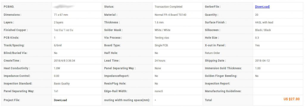
22 black and white PCBs for 25€ including a basic check and priority DHL airmail shipping. Can this really be true?
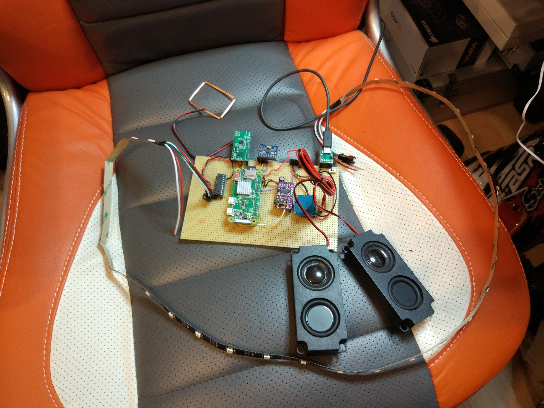
After I had a running prototype of M³ including a software proof of concept for every device, I wanted to design and order a professionally fabricated PCB as soon as possible. The weather was really good at that time of the year. That summer was one of the driest and hottest in Germany since a very long time (UPDATE: the next summer was even hotter, one of the warmest ever recorded). I allowed myself to open the balcony door while working midday. My kid was asleep anyway.
I decided to use KiCad which I hadn’t used before, so the learning curve was steep. The change rate was very high, too. It was my first time designing a board with more than a handful of daughter boards and connections. I had to reconsider decisions, redesign whole areas of the board (analog ground vs digital ground, ground planes, WTF?) more than once, discard features, add connections and shrink the board to a small form factor.
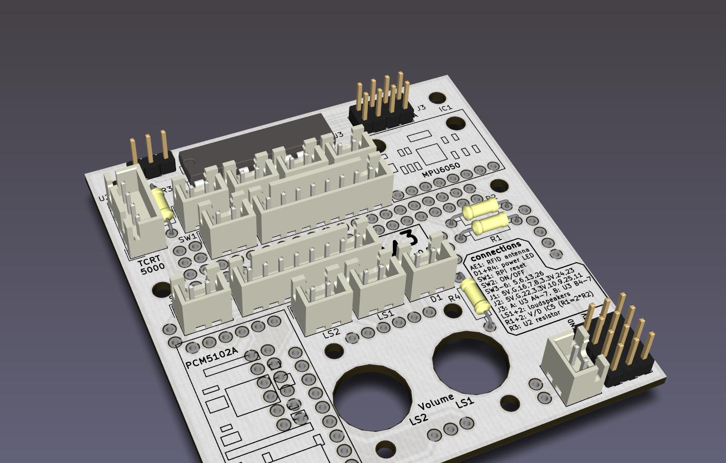

I think the latest design (v0.5) is small enough to fit inside many housings and still holds all the components necessary to be used for many different applications.
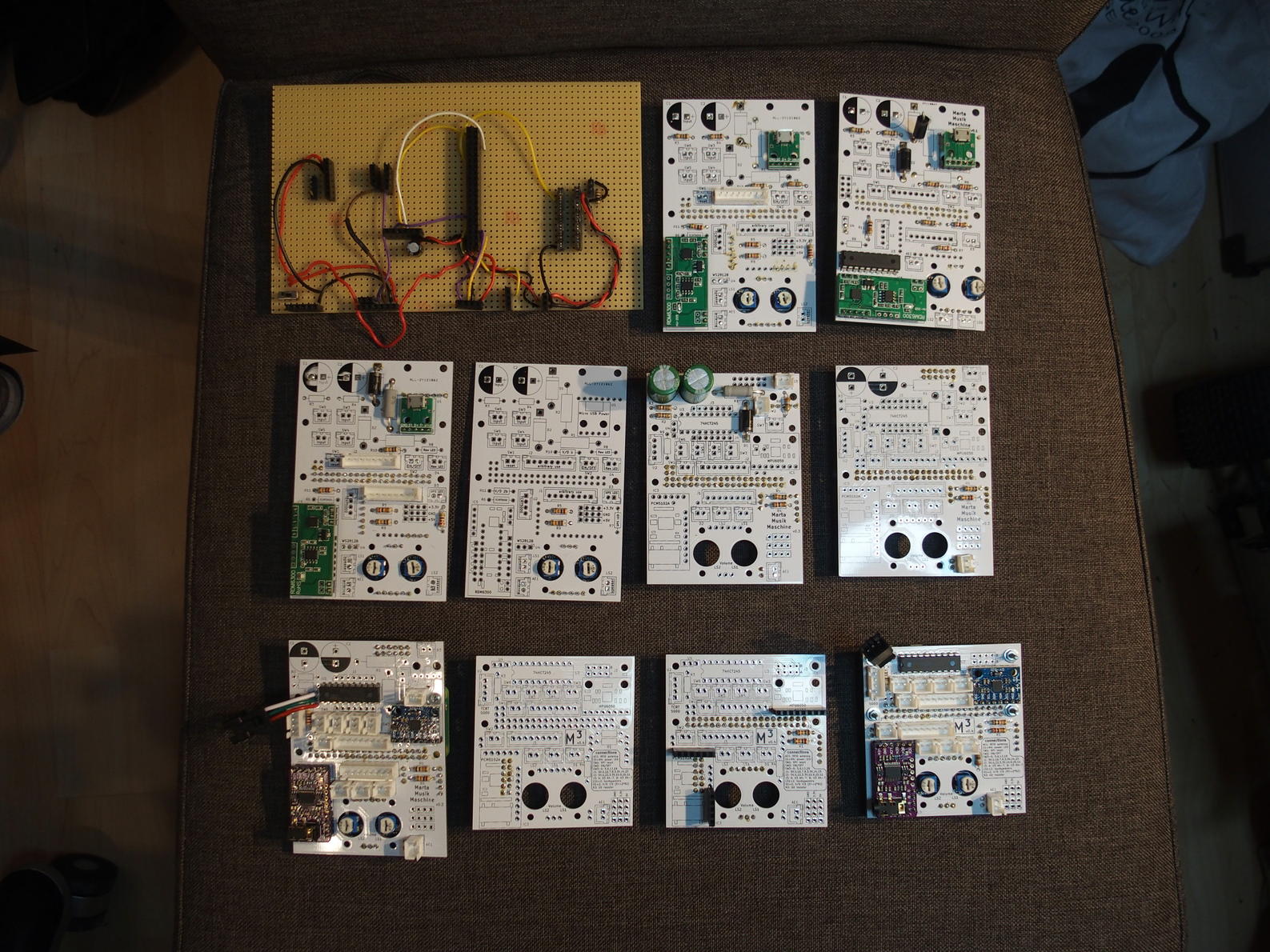
Ordering the boards in far east worked out flawlessly. I used a website called PCB Shopper to find the best (read: cheapest) offer. Prices change rapidly and fast, so I really advise everyone to sometimes have a look at these price comparison websites. The system suggested a company called ALLPCB. I uploaded a zip archive with all the gerber files in it. A basic check of the files was already included. 20 PCBs (I actually even got 22) were ordered, manufactured and sent around half of the world for 25€ including priority airmail via DHL. It only took four days until I held them in my hands. I know it’s not the ordinary case to order 20 boards, but the relative price drops the more boards you order.
If you live in Europe, I’m more than happy to send you an empty board if you are willing to defray the shipping costs. Just leave a message including your name, address and preferred shipping method. We’ll find a way.
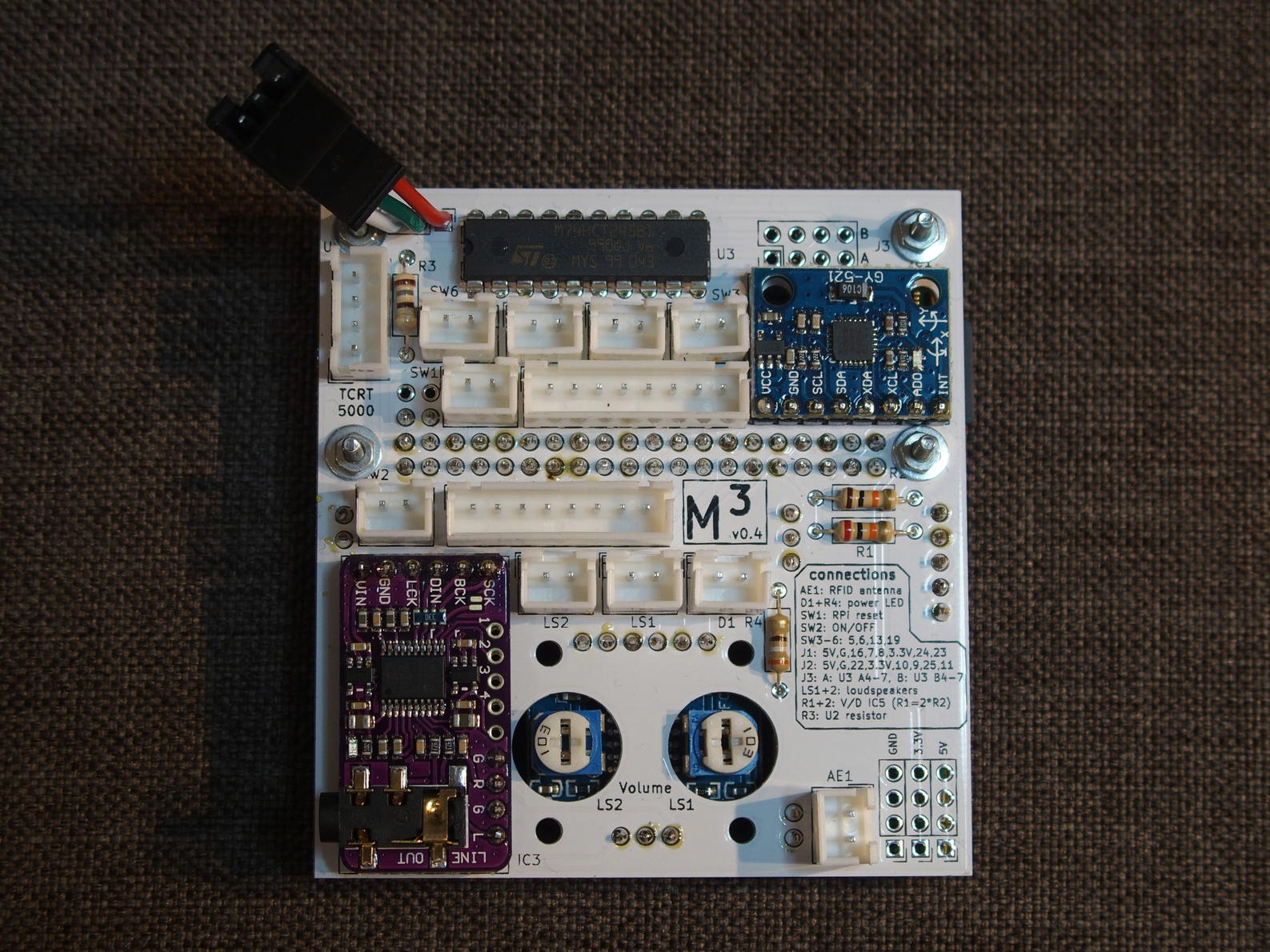
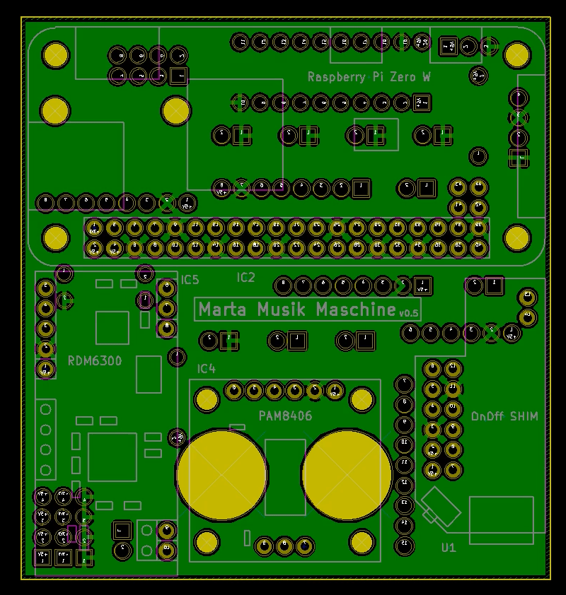
The PCB consists of two layers and needs to be populated from both sides, i.e. one has to solder electronic parts to the front and back side of the board. I opted for through hole components so that you don’t need much soldering experience or special equipment to assemble the board.
The PCB’s front is mainly designed to allow the external components like buttons, LEDs and the RFID antenna to be connected. Additionally the combined accelerometer/gyroscope as well as the sound board have their place on the front. It’s also possible to adjust the audio amplifier’s volume via its potentiometers. The front copper layer contains all the logic connections between the devices and serves as the power plane.
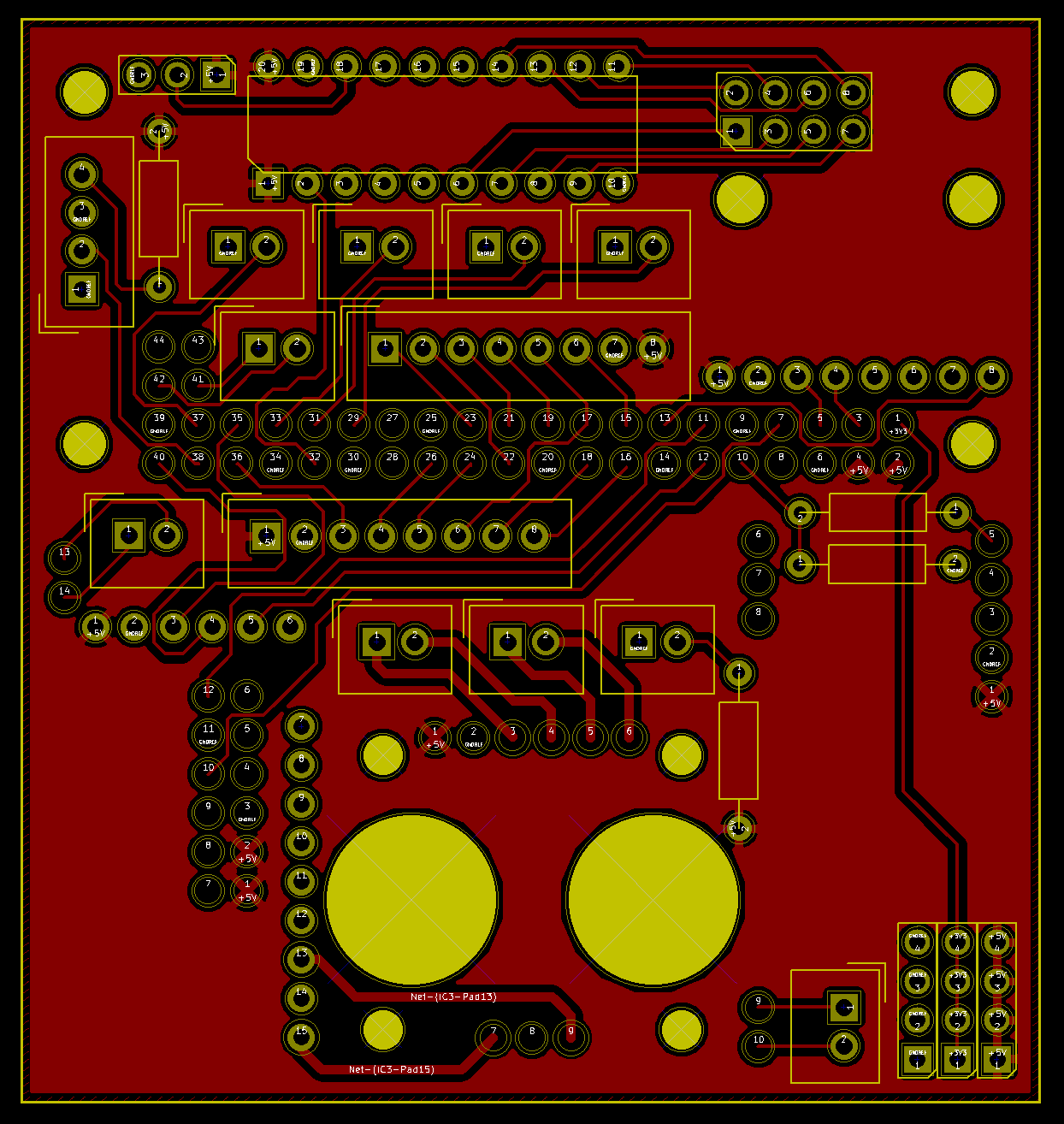
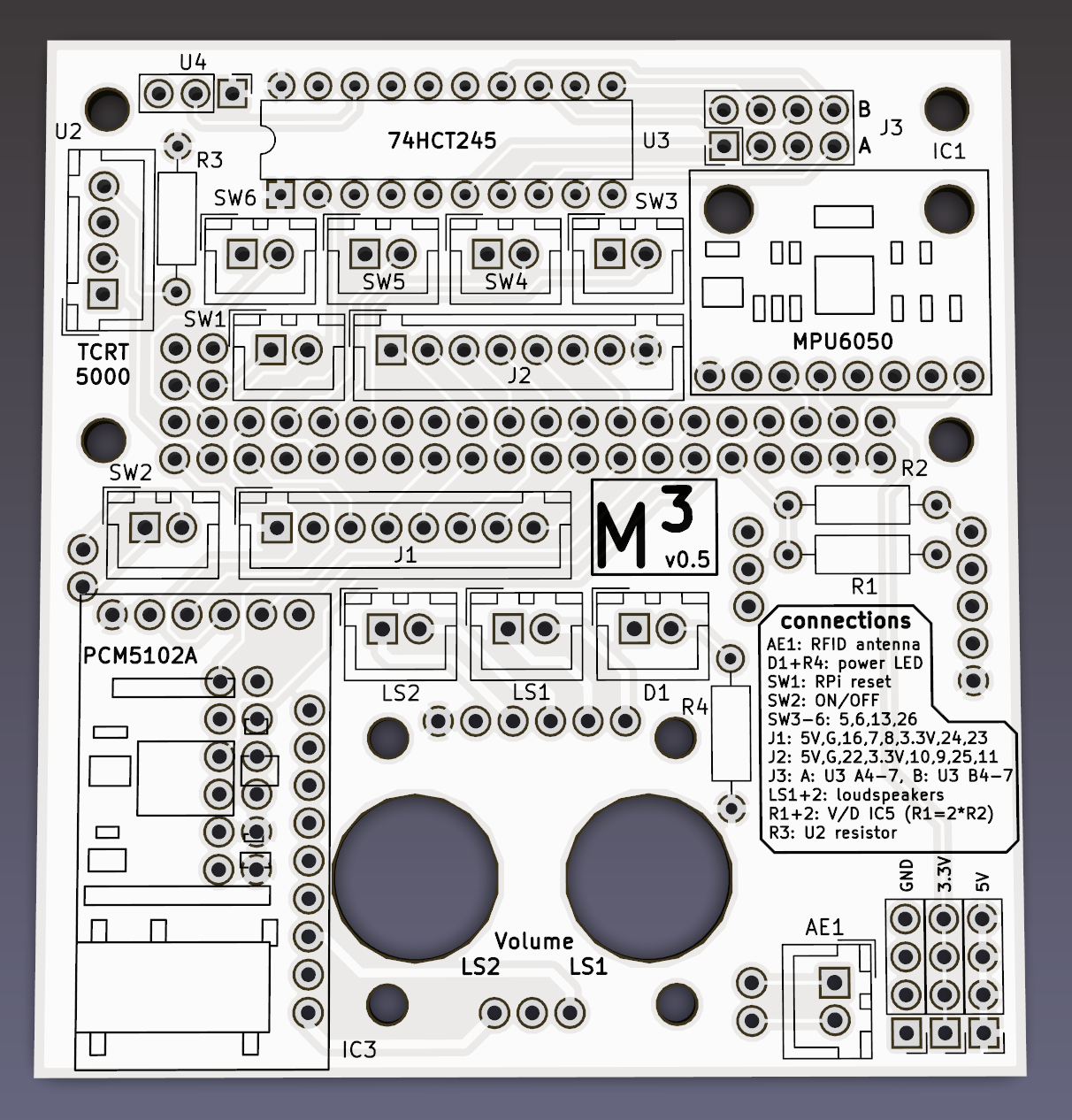

The back copper layer is the ground plane for all components (analog and digital) and does not contain any data lines. The RFID reader, ON/OFF shim, analog audio amplifier and most importantly the Raspberry Pi need to be soldered to the board from this side.


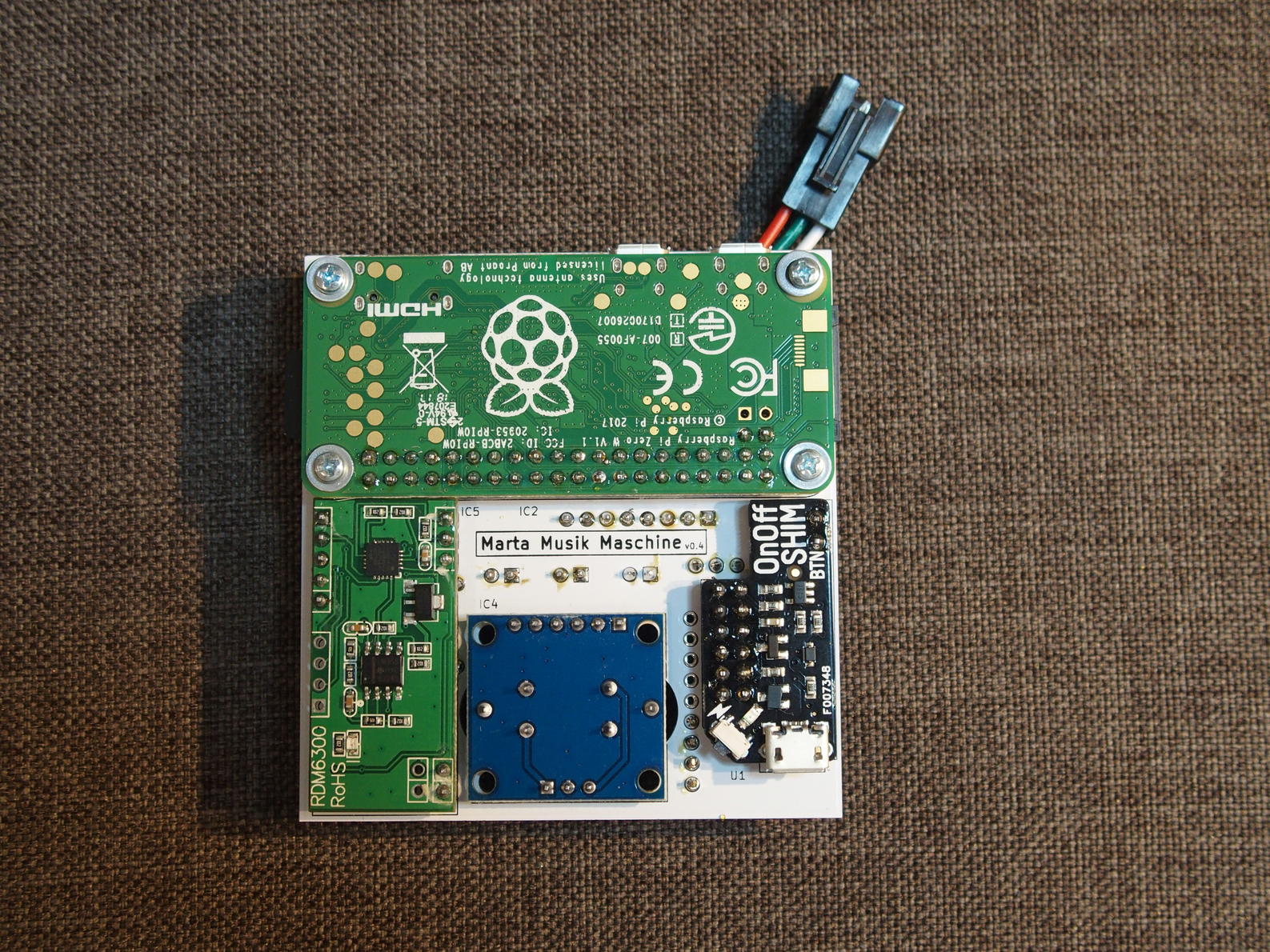
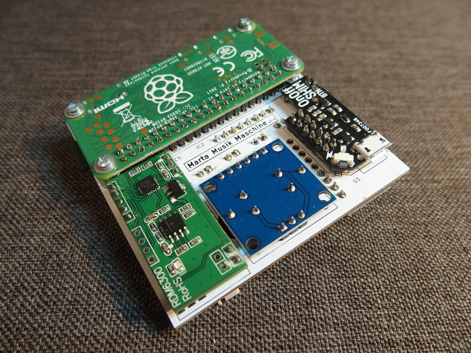
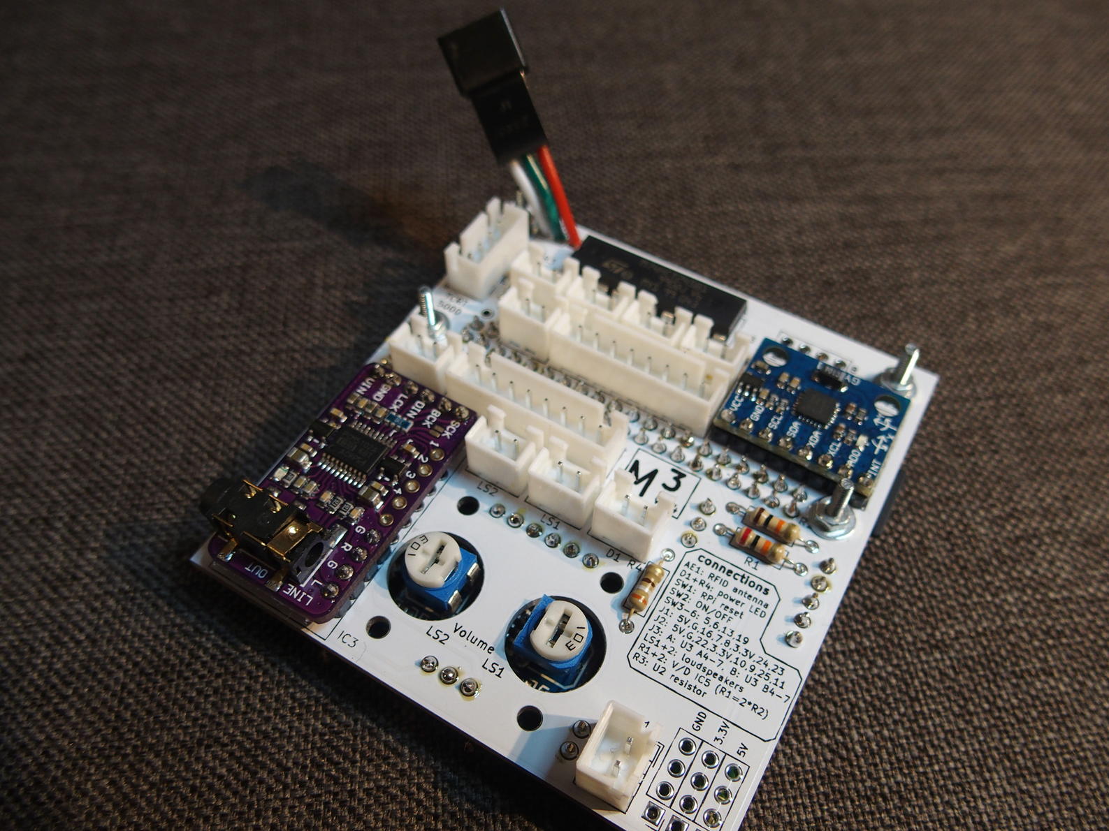
When assembling the main board one has to bear in mind that the order of the components while soldering is important. The ON/OFF shim and the sound card for example are located on opposite sides of the board. You need to solder the connectors to each side before mounting the daughter boards. If you’d solder the connector to the ON/OFF shim and then solder it onto the board, you would not be able to solder the sound card’s pins to the main board anymore.