I love these smart LED strips so much and used them in so many projects.
As I have already mentioned, it is a good idea to include some kind of feedback mechanism other than sound. We use the speakers as main application (namely to play music), but at the same time we want the child to be able to intuitively understand the inner state of our machine by means of light.
From the beginning I wanted the toy to be experienced with another sense, but deliberately excluded any kind of haptic feedback (like vibrating) for two reasons.
Even when the buttons are pushed, a user wouldn’t feel the vibration because the device is not being held when in use, but standing on a surface.
On the other hand didn’t I want to test the material for its durability by including a source of mechanical force. My children and their friends already push the device to its limit on a day-to-day basis by sometimes playing a little hard or throwing it around. The toy fell down on the floor quite a few times which didn’t do any harm yet. I didn’t wanna provoke manual interaction more than necessary as long as M³ is not ruggedized. Actually I am really surprised about what the device is able to take concerning mechanical stress anyways. That is why I opted for visual feedback.
Our Raspberry Pi is restricted not only regarding the number of pins but also their capabilities and the overall computing power. Nevertheless we still want many lights to shine up in different colors and smooth effects while not sacrificing too many pins. Sturdiness and an easy to use form factor are also important when deciding which product we pick.
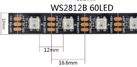
An LED strip is the first and only thing coming to my mind meeting all of these hardware requirements. Offered by many suppliers they come in (almost) any length with an RGB LED density of 30, 60 or 144 units per meter all speaking roughly the same protocol. The most famous representatives of their kind are probably the WS2811 and WS2812B, also known as NeoPixels. I think that is also the name of the protocol used to tell the individually addressable pixels which color they should show in what brightness.

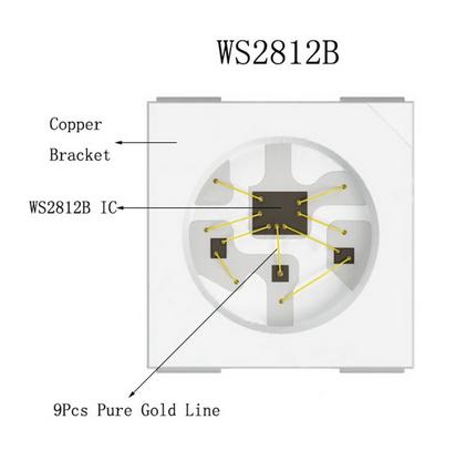

Please take the time to visit the Adafruit website mentioned above or use a search engine of your choice and have a look at a single of the ‘intelligent’ SK6812 RGB LEDs used in these strips. Every single light includes a tiny chip reading the data line, understanding the protocol and telling the LED (Red, Green and Blue) what to do.
PS: I’m always amazed by how small and fast man-made technical devices are. Just imagine what it means, that CPU manufacturers produce silicon chips working with 7nm transistors. Another astonishing read is this blog post setting computing periods (like a single CPU cycle) in relation to comprehensible times. Thinking about space and time always freaks me out (distances in the universe, quantum effects, relativity, etc). Sorry for wandering from the subject.
The Raspberry Pi uses a logic level of 3.3V. That means it indicates HIGH with 3.3V and LOW with 0V. The WS2812B strip however expects HIGH to be something like 5V while LOW is the same. Actually, a lot of electronic devices divide the logic level in three parts and accept LOW to be everything in the lower third of the allowed voltage interval and HIGH to be everything in the upper third. 3.3V (Raspberry Pi HIGH) is pretty close to 3.333..V (theoretically the lowest voltage interpreted as HIGH by the WS2812B). If I had to guess: I think, the setup would work without a level shifter. It would be pure luck if it did and I didn’t want to risk it.
That’s why we need another component, namely an active level shifter. The 74HCT245 chip is able to perform that task of transforming low level HIGH (3.3V) into higher level HIGH (5V) in no time. That’s why this particular chip is recommended when working with the fragile protocol used to communicate with the WS2812B strip.
The fore-cited LED strips are driven by a single data line and there is a superb library (supporting python) available completely compliant with our demand. It supports various ways to communicate with the chips inside the LEDs from userland. PCM is dismissed quickly as that would prevent us from using the I²S interface for the audio card. I probably should have gone with SPI. The pins are available and it seems to perform better than PWM in terms of CPU usage. On the other hand we couldn’t daisy chain any other devices on SPI, so the main benefit would be lost anyways. I haven’t done enough research before deciding to use PWM. Anyhow, we are only controlling 28 LEDs there shouldn’t be any noticeable differences.
All three methods of output manipulation (PWM, SPI and PCM) use DMA to transfer data. I guess otherwise the CPU couldn’t do anything else. SPI uses the technique in the kernel (there’s an SPI driver) while the other two methods access /dev/mem, which is not accessible for anyone but root in the default Raspbian configuration. That’s why we need to give all the programs trying to interact with the LEDs root privileges (I’m currently too busy [read lazy] to figure out an alternative).
What we need to do now in order to light up the LED strip is to first enable PWM on pin 12. The documentation for the device tree overlay states that PWM can only be used if analog audio is disabled. So be sure to either follow along the instructions on how to configure the PCM5102 sound board or disable analog audio yourself.
The Raspberry Pi Firmware readme file tells us that dt overlay function 4 enables single channel PWM. Actually it activates alternate function 0 for GPIO 12 which, according to the SOC documentation, refers to PWM0. In order to activate that very function, we need to append a dtoverlay to a boot config file.
pi@raspberrypi $ echo 'dtoverlay=pwm,pin=12,func=4' | sudo tee -a /boot/config.txt
pi@raspberrypi $ sudo reboot now
pi@raspberrypi $ lsmod | grep pwm

pwm_bcm2835             3254  0
After we’ve activated PWM on GPIO 12 and made sure that no other device tries to interfere with the PWM’s clock by disabling analog audio through the phatDAC installer script or manually, we are ready to clone, compile and test the aforementioned userspace library.
pi@raspberrypi $ sudo apt-get install scons
pi@raspberrypi $ cd /home/pi/
pi@raspberrypi $ git clone https://github.com/jgarff/rpi_ws281x.git
pi@raspberrypi $ cd rpi_ws281x/
pi@raspberrypi $ scons

scons: Reading SConscript files ...
scons: done reading SConscript files.
scons: Building targets ...
Version version.h
CC      main.o
CC      mailbox.o
CC      ws2811.o
CC      pwm.o
CC      pcm.o
CC      dma.o
CC      rpihw.o
AR      libws2811.a
RANLIB  libws2811.a
LINK    test
scons: done building targets.
Everything should be ready to tryout the LEDs by using the now compiled test program. We didn’t edit the main.c file where the default values are defined but instead pass the parameters according to our setup via command line. DMA channel 10 works fine on our Pi Zero W.
pi@raspberrypi $ sudo ./test --gpio 12 --dma 10 --strip gbr --width 28 --height 1 --clear
If you see a nice rainbow pattern moving around the LED ring, everything is prepared to go on and use python to talk to the strip.
We need to make a few dependencies available before actually building and installing the python API. The root user should be able to use the library without changing the PYTHON_PATH. Therefore we need to run the install step as super user. Afterwards you should be able to test the LED strip part of Marta.
pi@raspberrypi $ sudo apt-get install python-dev swig
pi@raspberrypi $ cd /home/pi/rpi_ws281x/python/
pi@raspberrypi $ python ./setup.py build
pi@raspberrypi $ sudo python ./setup.py install
pi@raspberrypi $ sudo python /home/pi/mmm/marta/LEDStrip.py

20:15:20.010 |   LEDStrip |    see the beautiful lights
20:15:20.013 |   LEDStrip |    ENTER or CTRL + C to quit
20:15:20.024 |   LEDStrip |    event: RAINBOW_DEMO
^C20:15:42.271 |   LEDStrip |    led strip terminating.
20:15:42.276 |   LEDStrip |    event: TERMINATE
If everything worked, you saw a multi color demo, all LEDs lighthing up and fading.