When prototyping and fiddling around, make sure to always have enough standard components at hand.
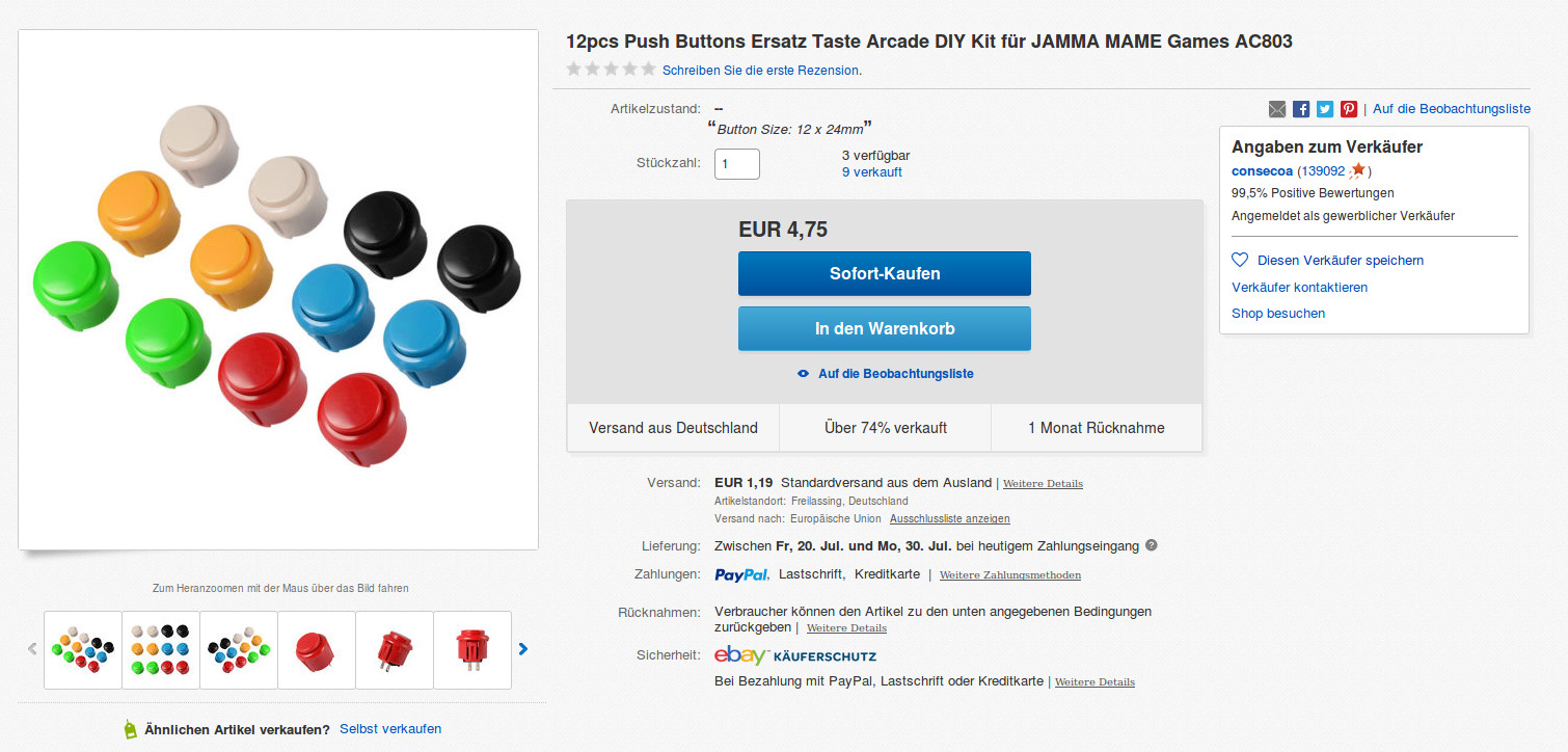
To let the little user interact with the device, we need a few buttons. The bigger the better I thought. Arcade machine buttons come in intense colors and have a perfect size. A price tag of 50ct per button seems reasonable. I found one particular product nice, because it is not as deep as a lot of the competitive products. Look for buttons with a diameter of 24mm and a depth of roughly 33mm.
You may want to think about debouncing the buttons in hardware or be lazy (like me) and just try to solve the problem in software. When something can be done in software, I most likely take that way.

To turn the machine on, we could use such an arcade button and later use the same component as a normal input. That’s what’s really cool about the OnOff SHIM. You could just add some logic to the software to power off the device (auto shutdown, button combination, special RFID tag, whatever).
But in my case, I wanted to use the SHIM’s trigger line to only act as a designated ON/OFF component. An arcade button is not suitable for that purpose. So I just grabbed a smaller push button of which I have dozens lying around. They’re always handy when it comes to control panels and have a price tag of only 15ct.

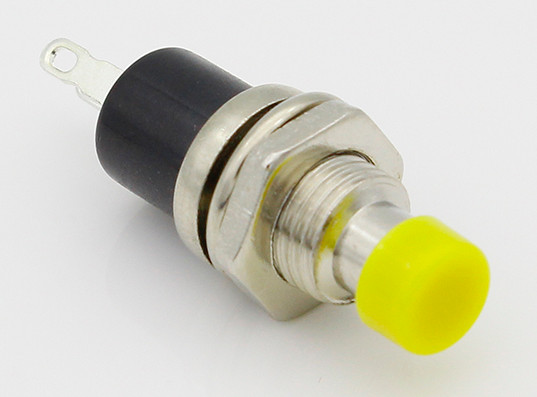
To prevent accidentally resetting the Raspberry Pi, I will use a standard 6mm push button and protect it within the enclosure, so that it’s only reachable with a thin stick. You can never have enough of these super cheap components. They only cost about 1ct per unit.

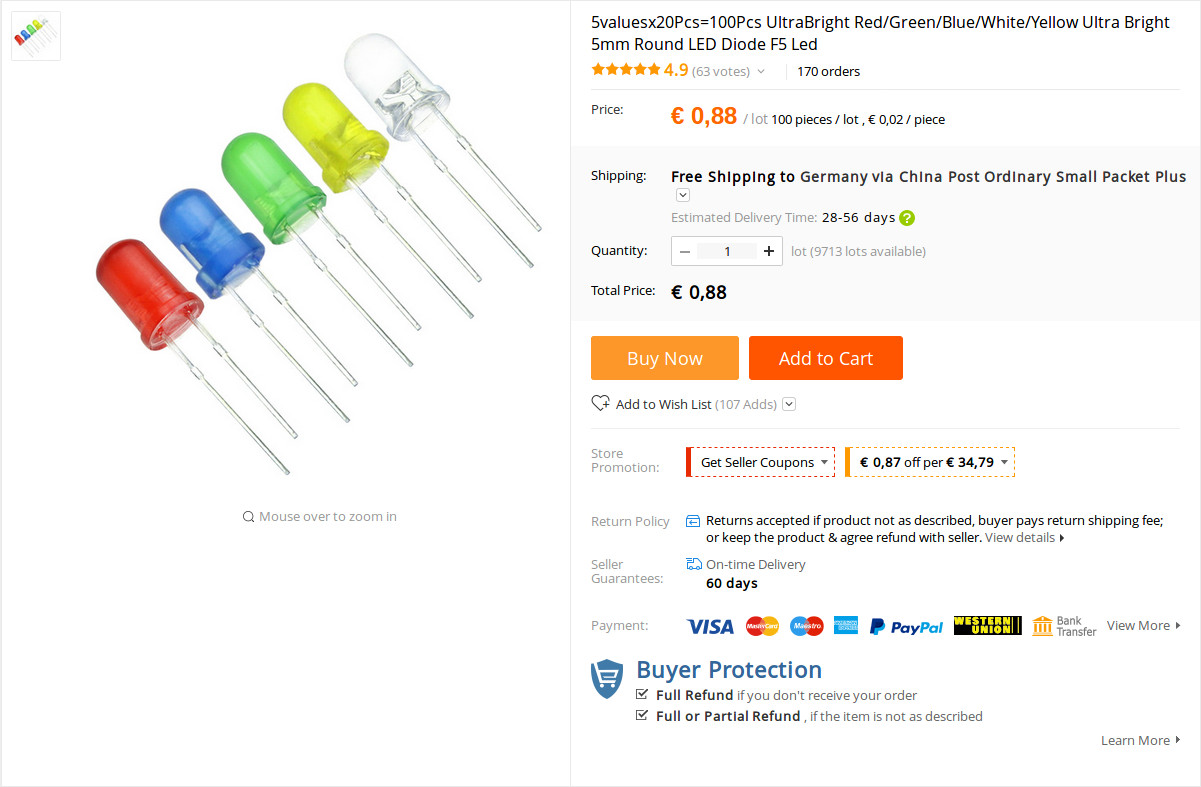
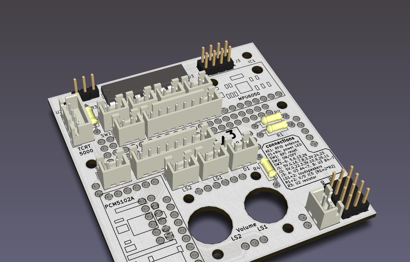
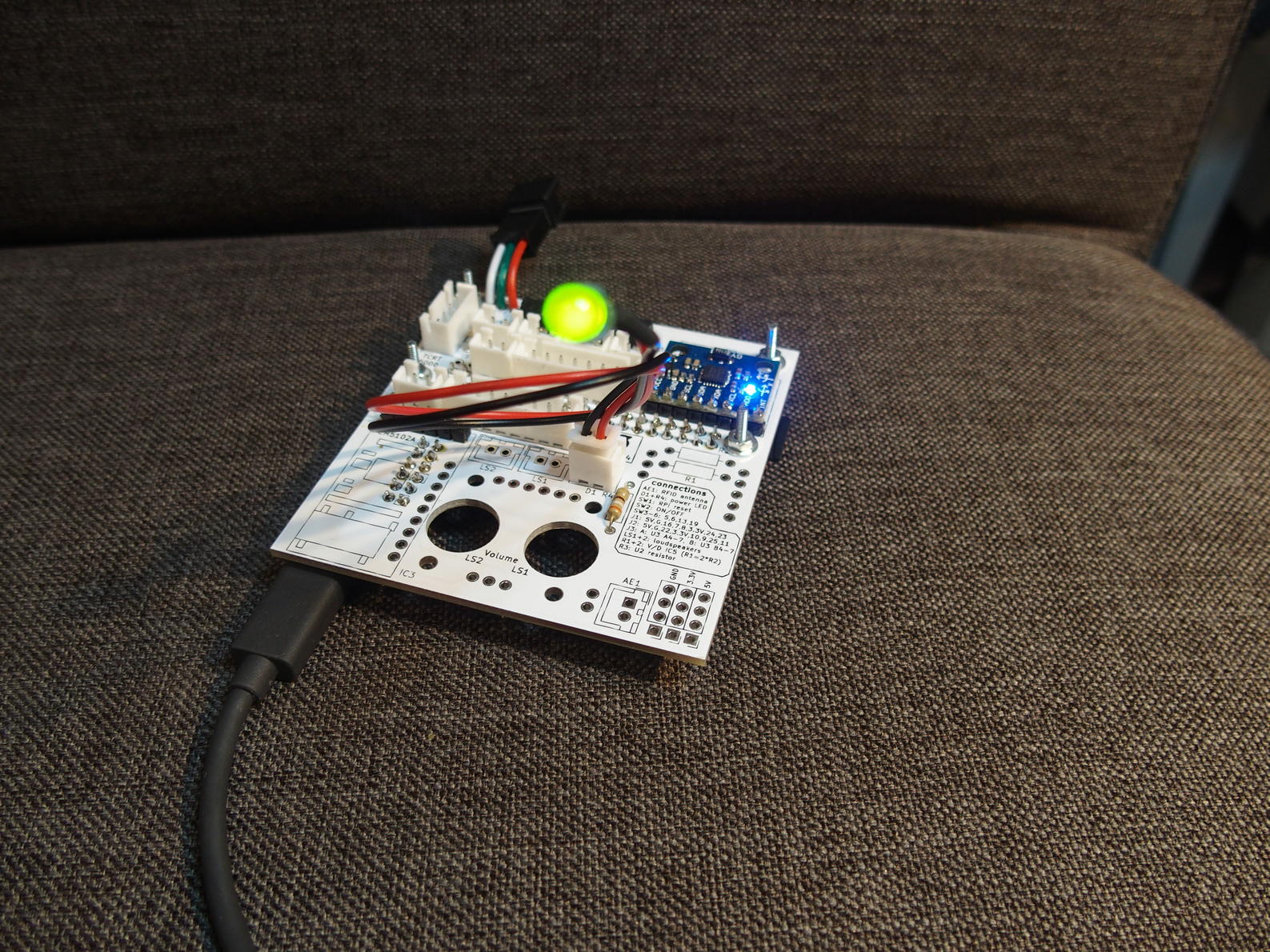
We have an unused input because we don’t need the TCRT5000 to detect the removal of a tag. I’m going to use that GPIO for another purpose, namely for a status LED. Also, the circuit offers the ability to connect a raw power indicator LED. Those and the voltage divider both need resistors to work. The prices can be neglected at under 1ct for an LED and only a third of a cent for a single resistor. That includes shipping around half of the world, which is insane and ridiculous at the same time.

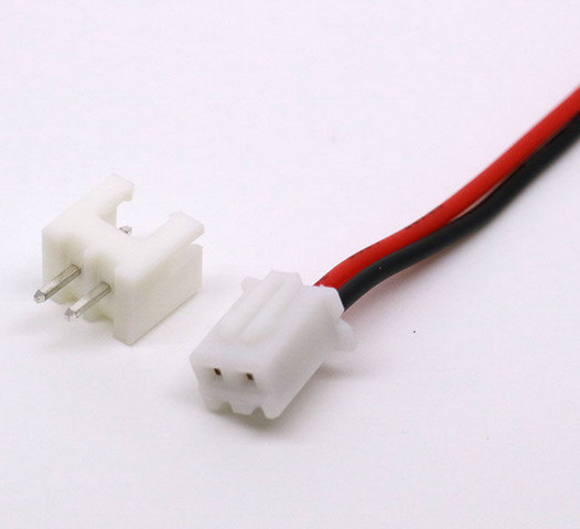
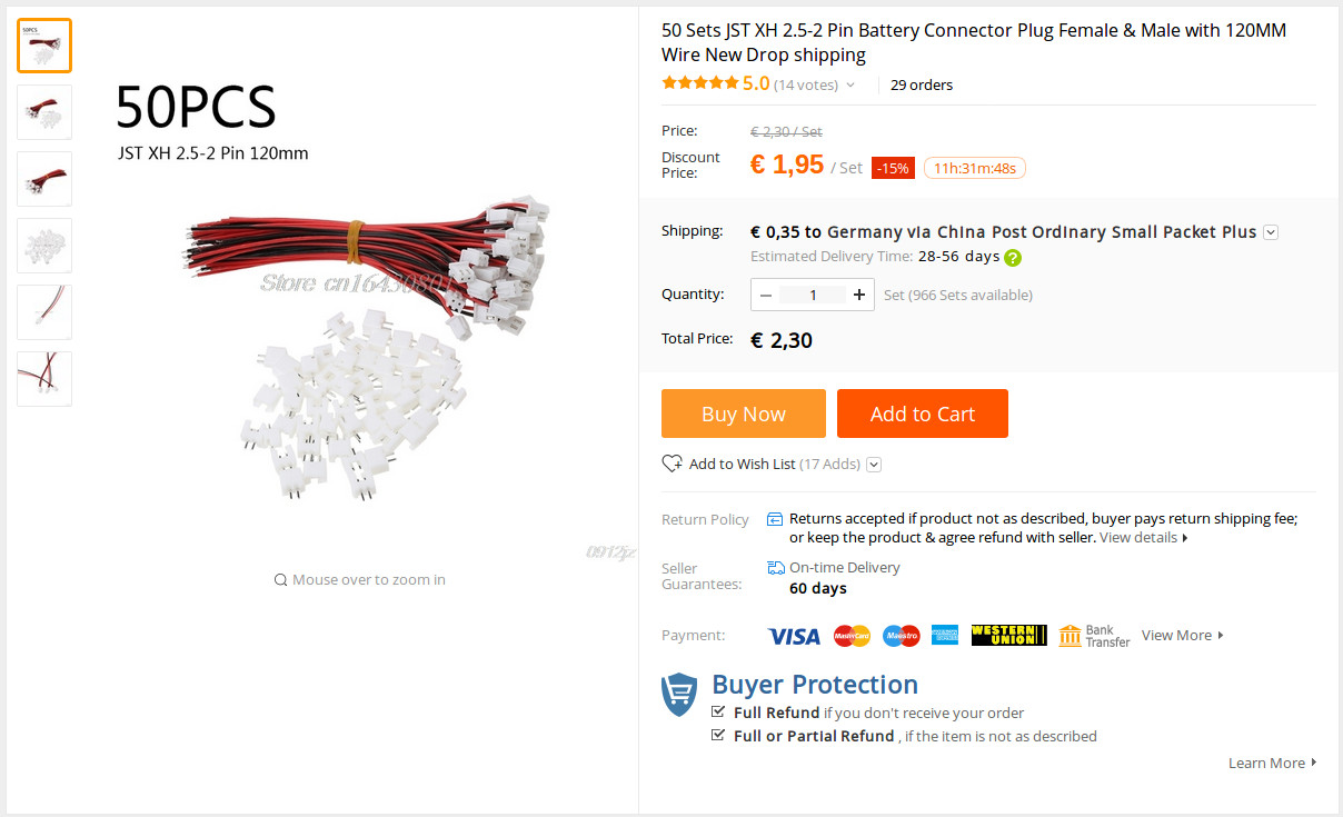
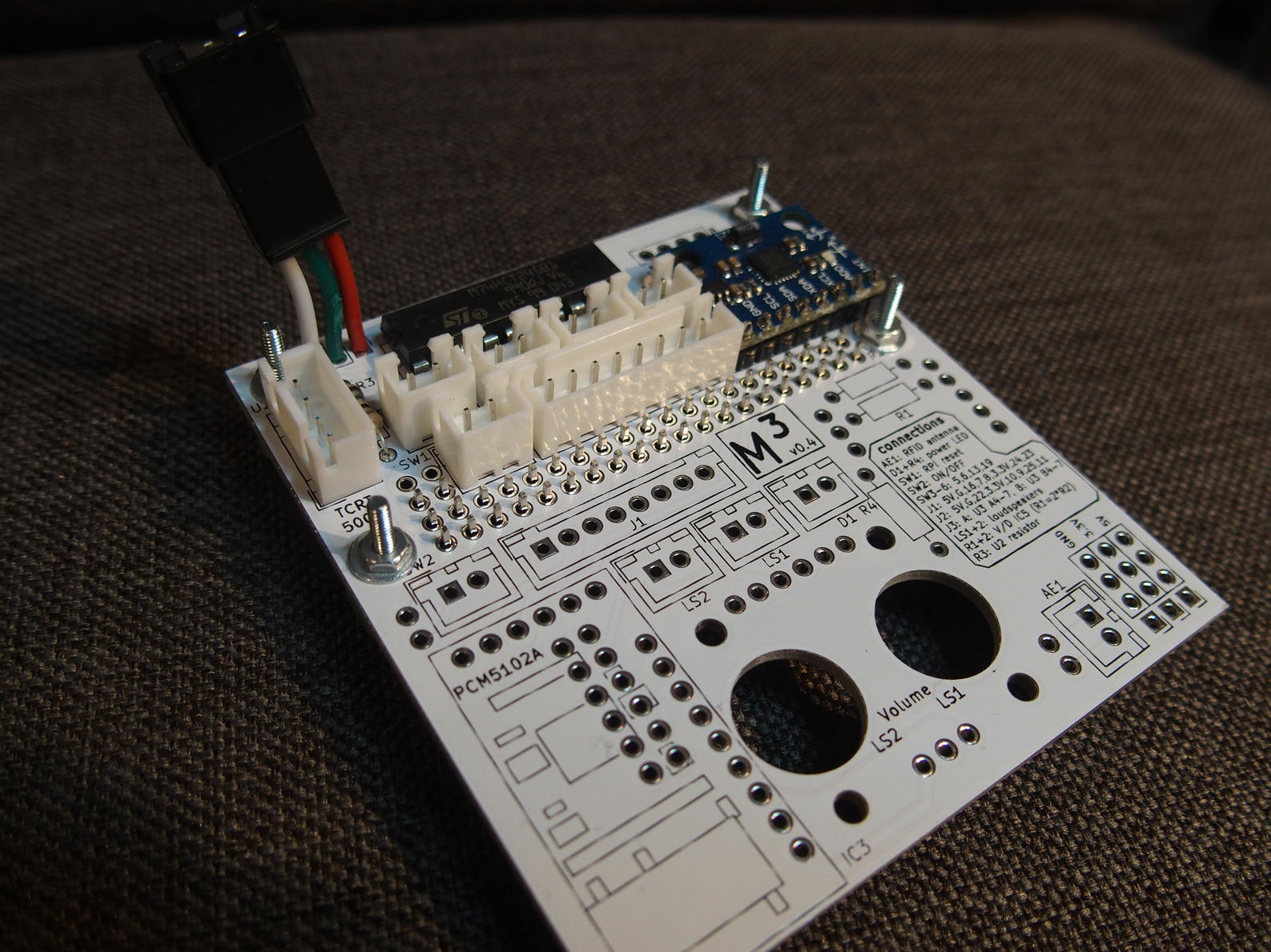
To get all of these components and the addon boards connected to the main PCB, we need a few male pin headers, connectors and cables. I opted for the JST XH type 2.54mm plugs because I find them convenient to use, they come in different pin configurations and hold on tight. You need the 2-pin option for most of the connections, the TCRT5000 port uses a 4-pin socket. I used an old 3S LiPo balancer plug for this connection, although I didn’t use the TCRT5000 sensor, but an LED. There are two optional 8 pin extension slots available on the main board. Both carry 5 currently unused GPIO data pins, +5V, +3.3V and GND. If you plan to use them, be sure to order some 8-pin JST XH connectors as well. Instead of using these three nice kinds of connectors, you could solder the cables directly onto the board, which I personally don’t like. However, to make all of the connections save to touch and bend, add some heat shrink tubing and you’re good to go.


Connecting the components should be a simple task left to the reader (that’s a lame excuse for: I don’t know what to write about it).
Let’s assume one has all the buttons and LEDs connected to the main board. Of course what’s next is to interface the physical part with the virtual world of software. To interact with the kernel, Linux provides a few virtual files at specific locations. One of them is the /sys filesystem. On the Raspberry Pi with Raspbian, it exposes parts of the hardware in a structured way. This mechanism for example allows the user to configure, read and write the GPIO pins just by reading or writing files.
Let’s for example turn on and off the LED on GPIO 20. We need to first export the pin so that a corresponding sub directory will be made available. We then configure the pin to be an output before actually changing its value.
pi@raspberrypi $ sudo echo 20 > /sys/class/gpio/export

pi@raspberrypi $ sudo echo out > /sys/class/gpio/gpio20/direction

pi@raspberrypi $ sudo echo 1 > /sys/class/gpio/gpio20/value

pi@raspberrypi $ sudo echo 0 > /sys/class/gpio/gpio20/value

pi@raspberrypi $ sudo echo 1 > /sys/class/gpio/gpio20/value

pi@raspberrypi $ sudo echo 0 > /sys/class/gpio/gpio20/value
The same approach can be applied for inputs accordingly. Execute the following commands and push the yellow button (GPIO 5).
pi@raspberrypi $ sudo echo 5 > /sys/class/gpio/export

pi@raspberrypi $ sudo echo in > sudo /sys/class/gpio/gpio20/direction

pi@raspberrypi $ sudo watch -n .1 cat /sys/class/gpio/gpio5/value
In our setup, this is actually only half the truth because unfortunately, the virtual filesystem doesn’t expose a file based method to enable the internal resistors connected to the pins. The board design depends on default pull-up resistors that we have to activate. We wanna use the program raspi-gpio to do that and subsequently read the button’s values.
pi@raspberrypi $ sudo apt install raspi-gpio

pi@raspberrypi $ raspi-gpio set 5,6,13,17,26 ip pu

pi@raspberrypi $ watch -n .5 raspi-gpio get 5,6,13,17,26

GPIO 5: level=1 fsel=0 func=INPUT
GPIO 6: level=1 fsel=0 func=INPUT
GPIO 13: level=0 fsel=0 func=INPUT
GPIO 17: level=1 fsel=0 func=INPUT
GPIO 26: level=0 fsel=0 func=INPUT
If this is working for you, you may want to try out the python part. Just execute the according script and push the buttons to produce output.
pi@raspberrypi $ python /home/pi/mmm/marta/Buttons.py

20:28:42.961 |    Buttons |    push the buttons!
20:28:42.964 |    Buttons |    ENTER or CTRL + C to quit
20:28:42.968 |    Buttons |    setting up gpio
20:28:44.073 |    Buttons |    push event on pin 26: 590
20:28:44.078 |    Buttons |    GREEN: 590 ms
20:28:46.438 |    Buttons |    push event on pin 5: 1758
20:28:46.441 |    Buttons |    YELLOW: 1758 ms
20:28:47.777 |    Buttons |    push event on pin 5: 104
20:28:47.780 |    Buttons |    YELLOW: 104 ms
20:28:49.641 |    Buttons |    push event on pin 6: 684
20:28:49.645 |    Buttons |    BLUE: 684 ms
20:28:50.017 |    Buttons |    push event on pin 6: 133
20:28:50.020 |    Buttons |    BLUE: 133 ms
20:28:56.158 |    Buttons |    push event on pin 17: 557
20:28:56.161 |    Buttons |    POWER: 557 ms
20:28:56.907 |    Buttons |    push event on pin 17: 120
20:28:56.911 |    Buttons |    POWER: 120 ms
20:28:58.008 |    Buttons |    push event on pin 26: 183
20:28:58.011 |    Buttons |    GREEN: 183 ms
20:28:59.065 |    Buttons |    push event on pin 13: 391
20:28:59.068 |    Buttons |    RED: 391 ms
^C20:29:12.246 |    Buttons |    terminating